- Home
- Unistrut Channels
- Unistrut A1000
Unistrut A1000
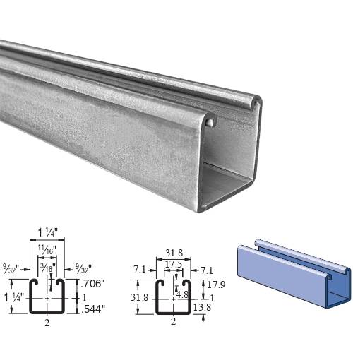
Unistrut A1000 - 1-1/4" X 1-1/4", 14 Gauge Strut Channel Stainless Steel
Robexstrut is a trusted supplier and dealer of high-quality Unistrut A1000 channels. Our products meet stringent quality standards and undergo several tests to ensure reliability. Unistrut A1000 is a versatile channel framing system available in various grades of stainless steel. Measuring 1 1/4″ x 1 1/4″, this single-type channel is available in 20-foot lengths catering to diverse applications.
- Chief Sourcing Partner for SS Unistrut A1000
- Trusted Supplier of Unistrut A1000 in India
- Stockist of Stainless Steel A1000 Strut in Mumbai
- Unistrut A1000 – 1 1⁄4" Framing System
Contact us today for high-quality A1000 Unistrut channels tailored to your needs!
Supplier of Unistrut A1000 in Mumbai, Get affordable Unistrut A1000 Prices, Trader of 1 1⁄4” Framing System A1000 Strut in India
Unistrut A1000 Specification
Standard Lengths:
- Up to 12 meters in length.
Dimensions
- Width: 1-1/4 inches (31.8mm)
- Height: 1-1/4 inches (31.8mm)
- 14 Gauge Nominal Thickness .075″ (1.9mm)
- Allowable Moment 2,170 In-Lbs (240 N•m)
Weight :
- Wt/100 Ft: 104 Lbs(154 kg/100m)
Finishes :
- Plain (PL)
- Stainless Steel (SS)
- Galvanized (either pre-galvanized or hot-dip galvanized) for corrosion resistance.
- Aluminum (EA)
Material :
- Stainless Steel Type 304 (SS), Type 316 (ST), (ASTM A240)
- Pre-Galvanized Steel (ASTM A653 SS GR 33, G90)
- Plain Steel (ASTM A1011 SS GR 33)
- Aluminum (ASTM B221, Type 6063-T6)
Welds :
- Welded channels are spot welded 2″ (51 mm) or 3″ (76 mm) on-center.
Ready Stock of A1000 Strut, Wholesaler of Stainless Steel A1000 Unistrut Channel in Mumbai.
Features & Applications of Unistrut A1000
- We provide custom sizes to meet specific requirements
- These channels eliminate welding and drilling for quick, adjustable, and reusable configurations.
- A1000 channels are corrosion-resistant which ensures long-lasting performance
- Unistrut A1000 channels are designed for quick installation and durability in various configurations.
Buy A1000 Unistrut in bulk for your next project—contact us for pricing
A1000 Unistrut Load Capacity
Bearing Loads on Unistrut A1000 Channel
 |
 |
 |
|
| Channel | Bearing Length 1 ¼" (31.8 mm) Maximum Allowable Loads - Lbs (kN) |
Bearing Length 1 ¼" (31.8 mm) Maximum Allowable Loads - Lbs (kN) |
Bearing Length 2 ½" (63.5 mm) Maximum Allowable Loads - Lbs (kN) |
| A1000 | 3,700 16.46 |
1,700 7.56 |
4,300 19.13 |
A1000 - Beam Loading (Imperial)
| Span (in) | Max Allow. Uniform Load (lbs) | Deflection at Uniform Load (in) | Uniform Loading at Deflection | Lateral Bracing Reduction Factor | ||
| Span/180 (lbs) | Span/240 (lbs) | Span/360 (lbs) | ||||
| 18 | 960 | 0.04 | 960 | 960 | 960 | – |
| 24 | 720 | 0.07 | 720 | 720 | 660 | 0.95 |
| 36 | 480 | 0.16 | 480 | 440 | 300 | 0.86 |
| 48 | 360 | 0.29 | 330 | 250 | 170 | 0.78 |
| 60 | 290 | 0.45 | 210 | 160 | 110 | 0.72 |
| 72 | 240 | 0.65 | 150 | 110 | 70 | 0.67 |
| 84 | 210 | 0.90 | 110 | 80 | 50 | 0.63 |
| 96 | 180 | 1.16 | 80 | 60 | 40 | 0.59 |
| 108 | 160 | 1.46 | 70 | 50 | 30 | 0.55 |
| 120 | 140 | 1.75 | 50 | 40 | 30 | 0.52 |
A1000 - Beam Loading (Metric)
| Span MM |
Max Allowable Uniform Load kN |
Defl at Uniform Load MM |
Uniform Loading at Deflection | ||
| Span/180 kN |
Span/240 kN |
Span/360 kN |
|||
| 600 | 3.2 | 2 | 3.2 | 3.2 | 3.1 |
| 750 | 2.6 | 3 | 2.6 | 2.6 | 2.0 |
| 1,000 | 2.0 | 5 | 2.0 | 1.6 | 1.1 |
| 1,250 | 1.6 | 8 | 1.4 | 1.1 | 0.7 |
| 1,500 | 1.3 | 11 | 1.0 | 0.7 | 0.5 |
| 1,750 | 1.1 | 15 | 0.7 | 0.5 | 0.4 |
| 2,000 | 1.0 | 20 | 0.5 | 0.4 | 0.3 |
| 2,500 | 0.8 | 32 | 0.4 | 0.3 | 0.2 |
| 3,000 | 0.7 | 46 | 0.2 | 0.2 | 0.1 |
A1000 - Column Loading (Imperial)
| Unbraced Height (in) | Allowable Load at Slot Face (lbs) | Max Column Load Applied at C.G. | |||
| K=0.65 (lbs) | K=0.80 (lbs) | K=1.0 (lbs) | K=1.2 (lbs) | ||
| 18 | 1,960 | 5,900 | 5,430 | 4,800 | 4,210 |
| 24 | 1,840 | 5,210 | 4,590 | 3,850 | 3,220 |
| 36 | 1,500 | 3,940 | 3,220 | 2,480 | 2,010 |
| 48 | 1,220 | 2,950 | 2,300 | 1,790 | 1,460 |
| 60 | 1,020 | 2,260 | 1,790 | 1,400 | 1,130 |
| 72 | 880 | 1,840 | 1,460 | 1,130 | 910 |
| 84 | 780 | 1,550 | 1,230 | 940 | KL/r>200 |
| 96 | 690 | 1,340 | 1,050 | KL/r>200 | KL/r>200 |
| 108 | 620 | 1,170 | 910 | KL/r>200 | KL/r>200 |
A1000 - Column Loading (Metric)
| Unbraced Height MM | Maximum Allowable Load at Slow Face kN | Max. Column Load Applied at C.G. | |||
| K = 0.65 kN |
K = 0.80 kN |
K = 1.0 kN |
K = 1.2 kN |
||
| 600 | 8.2 | 23.4 | 20.7 | 17.3 | 14.6 |
| 750 | 7.5 | 20.5 | 17.3 | 14.0 | 11.3 |
| 1,000 | 6.3 | 16.2 | 13.0 | 9.9 | 8.1 |
| 1,250 | 5.3 | 12.8 | 9.9 | 7.7 | 6.3 |
| 1,500 | 4.6 | 10.2 | 8.1 | 6.3 | 5.2 |
| 1,750 | 4.1 | 8.6 | 6.8 | 5.3 | 4.3 |
| 2,000 | 3.6 | 7.4 | 5.9 | 4.5 | ** |
| 2,250 | 3.3 | 6.5 | 5.2 | 3.9 | ** |
| 2,500 | 3.0 | 5.8 | 4.5 | ** | ** |
| 2,750 | 2.7 | 5.2 | 4.0 | ** | ** |
A1000 - Elements of Section (Imperial)
| Parameter | A1000 | |
| Area of Section | 0.305 | In2 |
| Axis 1-1 | ||
| Moment of Inertia (I) | 0.061 | In4 |
| Section Modulus (S) | 0.086 | In3 |
| Radius of Gyration (r) | 0.447 | In |
| Axis 2-2 | ||
| Moment of Inertia (I) | 0.078 | In4 |
| Section Modulus (S) | 0.125 | In3 |
| Radius of Gyration (r) | 0.506 | In |
A1000 - Elements of Section (Metric)
| Parameter | A1000 | |
| Area of Section | 1.96 | cm2 |
| Axis 1-1 | ||
| Moment of Inertia (I) | 2.53 | cm4 |
| Section Modulus (S) | 1.41 | cm3 |
| Radius of Gyration (r) | 1.14 | cm |
| Axis 2-2 | ||
| Moment of Inertia (I) | 3.25 | cm4 |
| Section Modulus (S) | 2.05 | cm3 |
| Radius of Gyration (r) | 1.29 | cm |
Unistrut A1000 Weight Chart
The weight of Unistrut A1000 (12 Gauge) depends on the material and finish. Below are the approximate weights per foot / meter of standard A1000 channels:
| Part No. | Length (ft) | Finish | Weight (lbs/ft) |
|---|---|---|---|
| A1000 | 10 | PG | 1.04 |
| A1000 | 20 | PG | 1.04 |
| A1000 | 10 | HG | 1.102 |
| A1000 | 20 | HG | 1.102 |
| A1000 | 20 | GR | 1.04 |
| A1000 | 10 | GR | 1.04 |
| A1000 | 10 | PL | 1.04 |
| A1000 | 20 | PL | 1.04 |
| A1000 | 10 | SS | 1.1 |
| A1000 | 20 | SS | 1.1 |
| A1000 | 10 | EA | 0.42 |
| A1000 | 20 | EA | 0.42 |
Alternate Framing Systems | A1000 Series (14 Gauge) – 1 1⁄4” Channel

Unistrut A1001
A1001 : 1-1/4″ x 2-1/2″ (31.8 mm x 63.5 mm), 14 Ga, Back-to-Back Solid Channel
Wt/100 Ft: 207 Lbs (308 kg/100m)
Allowable Moment 6,070 In-Lbs (690 N•m)
14 Gauge Nominal Thickness .075″ (1.9mm)

Unistrut A1001A
A1001A
1 1⁄4″ x 2 1⁄2″ (31.8 mm x 63.5 mm), 14 Gauge Channel, Side-to-Side
Wt/100 Ft: 207 Lbs (308 kg/100m)
Allowable Moment 7,930 In-Lbs (900 N•m)
Nominal Thickness .075″ (1.9mm)

Unistrut A1001B
A1001B : 1-1/4″ x 2-1/2″ (31.8 mm x 63.5 mm) , 14 Gauge Channel Combination
Wt/100 Ft: 207 Lbs (308 kg/100m)
Allowable Moment 7,930 In-Lbs (900 N•m)
Nominal Thickness .075″ (1.9mm)

Unistrut A1001C
A1001C
1-1/4″ x 2-1/2″ (31.8 mm x 63.5 mm), 14 Gauge Channel Combination
Wt/100 Ft: 207 Lbs (308 kg/100m)
Allowable Moment 6,760 In-Lbs (760 N•m)
Nominal Thickness .075″ (1.9mm)
Unistrut A1000 Channel Applications

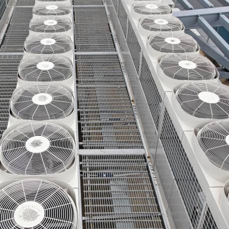

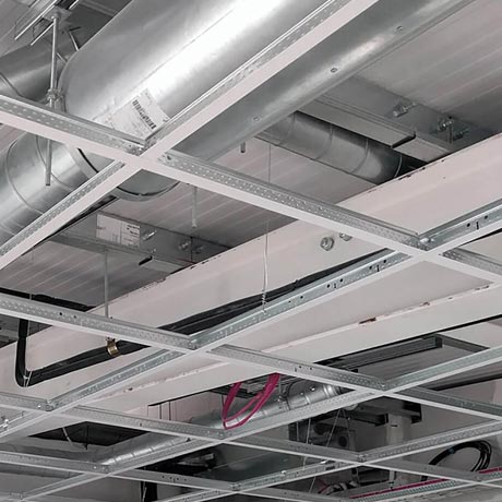
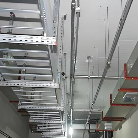


Product
- Unistrut Channel
- Stainless Steel Unistrut Channel
- Galvanized Unistrut Channel
- Slotted Channel Strut
- Gi Slotted Channel
- Back To Back Strut
- Solid Strut Channel
- Unistrut P1000
- Unistrut P1001
- Unistrut P1100
- Unistrut P2000
- Unistrut P3000
- Unistrut P3300
- Unistrut P4000
- Unistrut P4100
- Unistrut P4400
- Unistrut P4520
- Unistrut P5000
- Unistrut P5001
- Unistrut P5500
- Unistrut P6000
- Unistrut P7000
- Unistrut A1000
- Unistrut A3300
- Electro Galvanized Unistrut
- SS slotted channel
- SS Back to Back Channel
- Unistrut Plain Channel Bracket
- Unistrut Hardware / Fasteners
- Unistrut Channel Fittings
- Unistrut Pipe & Conduit Clamps
Related Product


